Evolution of the H400 Series Valves for HVDC LCC Schemes
The continued commitment to develop and evolve its products has enabled GE Vernova to maintain a strong position in a competitive HVDC market and provide an enhanced and flexible solution for new and replacement HVDC projects. The H450 HVDC thyristor-based valve is the latest such development, providing the ideal platform for future HVDC projects such as the Jeju Bipole 1 valve replacement in Korea.
HVDC converter station for Kepco's Jeju project installed on mainland
In Q1 2017, GE Vernova were successfully awarded an LCC HVDC Refurbishment Project in Korea. The project scope was for the replacement of the valves and controls of an existing 300 MW +/-180 kVdc Bi-Pole scheme. The scheme linked the mainland of Korea in Haenam to the island of Jeju. The key for GE Vernova to be able to undertake such a refurbishment project was having an LCC product portfolio flexible enough to provide an improved solution. Mark Donoghue, Principal Engineer at Grid Solutions, explains “This was critical for this type of scheme where there was a significant physical size and positioning constraint placed on the replacement valves due to the existing converter building which could not be modified”.
Haenam' HVDC converter substation building
H-Series valves evolving through the age
The solution was to use the latest development and evolution of the H400 series valves called the H450. This is the culmination of a number of major developments over the last fifty years. In order to understand where the H450 sits in the evolution of thyristor based HVDC valves, let’s look at the history of the GE Vernova valve family. The first-generation oil-cooled outdoor thyristor valve was developed in the late 1960s with a pilot installation commissioned in 1971 using three parallel connected stacks of 37 mm 4 kV thyristors. This was followed in the early 1980s by the H200 series valves which were forced air-cooled, air-insulated indoor valves using 2 parallel 56 mm 4 kV thyristors per level. In the late 1980s, this was followed by the H300 series valves, the first water-cooled indoor floor mounted valve utilizing single 5.2 kV 100 mm thyristors per level. Finally, the latest H400 series suspended water-cooled indoor valve using single 8.5 kV thyristors with options for 100 mm or 125 mm thyristors per level was introduced in 2003. This was developed further into the H420 in 2010, allowing for higher transmission voltages and the possibility to use 150 mm thyristors, and the latest evolution is the H450 introduced in 2017. This improvement of the LCC valve allows GE Vernova to be more competitive on the HVDC LCC market, by deploying the H450’s reduced physical size valve, without affecting electrical performance.
H400 valve module
H-series provides the core power converter technology in the Jeju Bipole 1 HVDC scheme
The key purpose of the Jeju Bipole 1 refurbishment project is to provide stable and economical power supply by a main equipment replacement and performance upgrade in order to meet an increase in continuous power demand. The existing equipment was originally installed by GE Vernova in 1994 and therefore around 25 years old. The original valves were based upon the 3rd generation H300 thyristor valve.
“This valve is the core power converter technology for the traditional, and mature, LCC HVDC market. The present H400/H420 valve technology has been in use for about 15 years and was Grid Solutions’ first suspended valve design. The technology has been used for a variety of HVDC projects, including back–to–back and point–to–point projects, the latter including submarine cable and overhead lines (OHL) projects. The valve has operated at DC voltages up to ± 800 kV on the Champa-Kurukshetra project in India and is able to accommodate 100 mm, 125 mm and 150 mm thyristor devices”, says Donoghue.
Zoom on the H450 series valve
In common with all valves from the H300 series onwards, GE Vernova’s latest H450 valves use direct liquid cooling which enables a single-circuit system with either pure deionized water or a water/glycol mix, depending on ambient temperature conditions at site. The valves are air-insulated and suspended within a controlled environment. By suspension mounting the valves, the mechanical stresses are reduced, which is of particular importance for applications in seismic areas. However, in some cases, such as pre-existing structures with inadequate suspension facilities, the valve may be floor mounted by using ceramic or composite support insulators. The valves employ high power thyristors, together with associated gating, damping and grading circuits, arranged in 6- or 12-pulse converter groups. According to the application type, thyristors with different voltage ratings and diameters can be easily accommodated.
New H450 series, the need for a new valve module with same performance
In recent years, GE Vernova further evolved the H400 series valve with a "re-packaging" design of the existing H400 module and H400 valve arrangement. “The main scope of this development was the re-design of the module without affecting the electrical performance of the existing H400 design”, states Donoghue. He adds, “Hence the same thyristor options, the same di/dt reactor and the same damping resistors have been reused on the new H450 module”.
The H450 development project followed the same New Product Introduction process as usual, with different technical gates from the conceptual designs to the industrialized product for the first H450 contract project in South Korea with KEPCO BP1 refurbishment scheme.
H450 valve hall used for Jeju HVDC Bipole 1 renovation project
But so much lighter and smaller! The new thyristor clamped assembly is key
The key part of the H450 development centered around what is called the Thyristor Clamped Assembly (TCA), an assembly that houses the thyristors and water cooled heatsinks. In the existing H400 series valves there were two separate but identical TCAs; however, as part of the H450 development these were combined into a single clamped assembly containing twice as many thyristor levels. The key components that make this possible are the filament wound glass reinforced plastic (GRP) banded straps used to provide the large clamping forces required by the modern-day power thyristors used in HVDC. Depending upon the size of the thyristors (diameter) the maximum clamping force can range from 90 kN for the 100 mm diameter devices up to 200 kN for the largest 150 mm diameter devices. A notable feature of the band design that was developed for the H450 was that only one design was needed, irrespective of the size of thyristor used, which was not the case for the original H400 series valves. Another key change within the TCA was the reduction of overall thickness of the thyristor heatsinks, enabling space saving compared to the original design. To ensure electrical continuity through the valve/TCA when we do not require a full complement of thyristors fitted into some of the modules, dummy thyristors are used. In a matter of fact, the total number of thyristors required for the project valve is not a multiple of 12 (the maximum that can be fitted in a TCA). That’s where an actual thyristor is replaced with a copper block, also called dummy thyristor.
Thyristor clamped assembly (TCA) with thyristors (THY), dummy thyristors (Dummy THY) and heatsink (HSK)
The development of the single thyristor clamped assembly was the enabler to make significant reductions in the overall dimensions of the valve module; a key building block of an HVDC valve. A reduction in dimensions of some 38% and a reduction of weight of 20% were achieved, giving a significant flexibility in the valve arrangements and size of valve building. This size reduction was also key in the layout of the valves for the KEPCO valve replacement project.
On the valve structure stand-point, two significant improvements have been achieved.
- The reduction of the electrical clearance around the valve thanks to the new shape of the corona shields (see sidebar article).
- The addition of a second valve arrangement known as “in-line” where the modules are positioned end-to-end (see cover picture). By comparison, the traditional H400 series use a “square” arrangement where the modules are side-by-side.
Haenam HVDC LCC converter station In Korea: Valve hall
The new arrangement provides an opportunity for GE Vernova to improve the width of the valve hall using the in-line valve arrangement when other equipment, such as the converter transformer and busbars, dictate the length of the valve hall. By adding the choice of using an “in-line” arrangement or the existing “square” arrangement for either suspended or floor mounted options with two, four or eight valves per Multiple-Valve Unit, GE Vernova’s HVDC LCC product provides flexibility for the transmission operators.
Intensive type testing process according to IEC 60700-1
The design of a thyristor valve is a complex, multi-disciplinary process involving a range of engineering disciplines including power engineering, power electronics, analog electronics, semiconductor physics, heat transfer, fluid mechanics and mechanical and structural engineering. As there are no standards to follow for designing the HVDC value, GE Vernova relies on the vast experience and solid design practices gained through over 50 years in the HVDC industry. Modern thyristor valves are relatively standardized, that is to say that the bulk of the real design work is carried out during the product development phase, such that applying the valves to a particular project is a relatively straightforward matter. At its simplest, the work involved for a particular project may just involve adapting the number of series-connected thyristors according to the voltage rating requirements imposed by the overall system design. For the introduction of a new product and first project implementation this may not be so straightforward. We therefore sought to minimize manufacturing and testing risk by producing a batch of valve modules ahead of type testing.
While there are no specific standards for the design of HVDC valves, this is not the case for the testing of HVDC valves. IEC 60700-1: ‘Thyristor valves for high-voltage direct current (HVDC) power transmission – Part 1: Electrical testing’ defines the test program for the valve and covers two broad categories: dielectric tests and operational tests. The type tests form an important part of the design verification process as well as customer project requirements. In addition, the standard covers both production routine testing and sample testing.
When a new thyristor valve design has been produced or a previously tested valve design is modified, a program of type tests must be performed. Type testing of thyristor valves is complex, specialized and time-consuming. Some parts of it require extremely specific and expensive test circuits for which only a few serious players in HVDC can justify investment in. All thyristor valves are subjected to comprehensive routine testing in the factory. The purpose of this test program is to prove that the thyristor valves have been correctly assembled. It aims to identify wiring connections that have been incorrectly made, grading components that are out of tolerance, gate electronics that are malfunctioning, blockages in the cooling circuit, joints between the thyristor and heatsinks, etc.
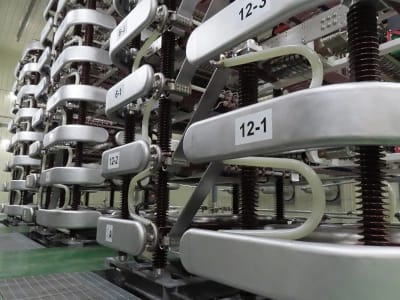
For the KEPCO valve replacement project the valves needed to be floor mounted and sited within the converter building, essentially as in the original installation. The reduction in size, weight and increased flexibility of the H450 design made this possible. The figure below shows the valve arrangement. Each of the three structures are known as a quadri-valve (i.e. a structure comprises four valves) and forms the overall 12-pulse converter bridge and represents one pole end of the scheme.
H450 series valve arrangement
Highlights
- GE Vernova’s new H450 design is 38% smaller, and 20% lighter than the H400 product, despite using the same main components (thyristors, di/dt reactor, damping resistors.)
- The number of parts per module has been reduced by 25%. This allows the manufacturing line to be more efficient, quicker and more controlled.
- The maintainability at site is simplified, with easier access to the main components to replace during a planned maintenance outage.
Zoom on the corona shields
Design enhancement of the corona shields
Since the late 1970s, all commercial HVDC valves have been air-insulated; that is to say, the insulation between the valves and earth is achieved by using air instead of a higher-performance dielectric medium such as oil or SF6. This is mainly because of the large physical size of the valves and the need to access the valve components at regular intervals to replace failed components.
As HVDC transmission voltages have increased sharply in the last decade (from 500 kV to 800 kV or even higher), the size of air clearances needed around the valves has also needed to increase, and since air clearances increase non-linearly with voltage, the air clearances around the valve are now having a dramatic effect on the size of the valve hall. The valve hall is a very large building with stringent requirements on air quality and there is therefore a considerable economic incentive to reduce its size.
An external profile as smooth as possible
For high voltages and large air clearances, the design of the corona shields at the top, bottom and sides of the valve is of paramount importance. The aim of these corona shields is to make the external profile of the valve as “smooth” as possible, avoiding regions of high curvature which will lead to localized areas of high electric field and an increased risk of flashover.
The design of the predecessor H420 valve module was carried over from the earlier H400 valve and only the external corona shields were changed, leading to relatively limited shielding, and the need for long clearance distances.
Colin C. Davidson, Consulting Engineer at GE Vernova's Grid Solutions business, explains, “the H450 valve is a mechanical “re-packaging” of the H420 valve, using the same electrical components but in a better and more compact mechanical layout, considering the external corona shielding from the outset. The performance of the H450 valve has been verified by undertaking a series of “50% flashover voltage” tests (U50 tests) which involve repeatedly applying switching impulses to the valve structure at gradually increasing voltages and for a range of different clearance distances”. The H450 valve has been demonstrated to achieve dramatically smaller electrical clearance requirements than its predecessor, more than a 50% reduction for the so-called “inline” configuration at the highest voltages (pictured).
U50 Test campaign